How Wearable IoT Devices Benefit Healthcare | Voler Systems
Today more than ever, wearable IoT devices are playing a significant role in the...


The most common sensor is a temperature sensor, and the most common temperature sensor is a thermocouple, and yet most people do not know how a thermocouple works. They are one of the most complex sensors to measure, yet they are very low cost and rugged. If you do not understand cold junction compensation you probably have errors larger than what is specified for your device. First some basics, then we will discuss some serious common problems.
A thermocouple generates a voltage that changes with temperature, so at a basic level, a device that can measure voltage can measure a thermocouple signal. This is called the thermoelectric effect or the Seebeck effect, and is caused by placing dissimilar metals in contact to form a junction. The voltage is very small, however. The most common thermocouples, types E, J, K, N and T change about 30 to 60 microvolts per degree C change in temperature. A data acquisition device that has a 10 V full scale range and 16-bit resolution can therefore only detect a change of 3 to 5 degrees C or larger. Thus amplification is usually required.
The more exotic thermocouples, types B, R, and S change about 10 microvolts per degree C change in temperature. The same 10 V 16-bit data acquisition device can only detect a change of 15 degrees C or larger with these types.
With amplification the full scale range can be 100 mV or less, yielding a resolution of about 0.05 degrees C on the common types and 0.2 degrees C on the exotic types of thermocouples. With a 100 mV full scale range temperatures can be measured from -270 to +2300 degrees C, depending upon the thermocouple type (see table 1 below).
Another difficulty with thermocouples is that the voltage does not change linearly with temperature. Unlike many devices, the linearity error is large, over 1% for the common thermocouples, and is even larger below zero degrees. For some types the voltage does not even change with temperature in part of the range. The B type is not usable near or below room temperature because of this.
The linearity must be corrected for almost any practical use of a thermocouple. There are two methods: look up the temperature in a look-up table of voltage vs temperature, or calculate the temperature using an equation. Both of these can be highly accurate. The look-up table is two columns of numbers, one is voltage and the other is temperature. The temperature is found by locating the two nearest voltage readings and calculating a straight line approximation between them to find the temperature. A table of about 100 entries or more is usually needed to keep the linearity error less than 0.1 degree C.
The calculation, on the other hand, is a high order exponential equation of the form:
T = c0 + c1V + c2V2 + c3V3 + c4V4 + cnVn
Where T is the temperature, V is the voltage, and c0 to cn are constants.
Each added term of higher order (cnVn where n is the order) increases the accuracy. Some thermocouples require more than a tenth order equation to keep the linearity error less than 0.1 degree C.
The linearity correction is normally done in software on a PC where the complexity of the equation is not a problem. For devices not connected to a PC, such as stand-alone meters, temperature controllers, or many dataloggers, the linearity correction is done by a microprocessor in the device, where a look-up table may be the easiest. A few extremely simple devices without a microprocessor do not have linearization.
The thermocouple has a unique additional correction called cold junction compensation. It is unique among temperature sensors, and it is often misunderstood. The reason for the compensation is that the thermocouple only reports the relative temperature difference between the sensing end and the terminals where it is connected. An absolute temperature sensor must be used to measure the temperature of the terminals. Long ago this was done with a thermocouple in ice water, thus a cold junction.
A cold junction sensor is typically a semiconductor sensor or a thermistor located at the connection terminals. The temperature measured by the cold junction sensor is added to the temperature of the thermocouple. This is rather simple, but there are subtle ramifications.
Because of the cold junction compensation, the connection of thermocouples is more complex than other sensors. The wire type and location of the connections is important. The voltage generated by a thermocouple results from two dissimilar metals being placed in contact, which generates a voltage due to the thermocouple effect. The voltage changes with temperature.
Each lead of the thermocouple must have the same type of wire from the sensing end to the terminals where the cold junction sensor is located. If a copper wire is connected to the non-copper thermocouple wire, another thermocouple junction is created, and the voltage across the new junction changes with temperature. The voltage measured would be the result of the two junctions, not what was expected. The cold junction sensor must be located where the thermocouple wire changes to copper, usually inside the measuring device.
To avoid problems always use thermocouple wire from the thermocouple to the connection at the cold junction sensor. Extension grade thermocouple wire is sold for this purpose. It is less expensive than ordinary thermocouple wire.
The error in a thermocouple measurement is the sum of the following errors:
The first error is specified by the thermocouple manufacturer. The second and third are normally included in the specifications for the measurement device (though often the cold junction sensor error is listed separately or omitted).
The forth error is rarely specified, and it is often the largest error. It is the error from assuming that all the thermocouple connections are at the same temperature as the cold junction sensor. It is a difficult error to specify, because it depends upon the temperature gradients near the connections. Worst of all, unlike the other errors, which are repeatable, and can be removed with careful calibration, the this error changes with in an unpredictable way, causing errors that are likely to be unnoticed. As a result many people think they have higher accuracy than they actually do when using thermocouples.
The error is greatly reduced when there is a heat sink that keeps all the connections at the same temperature. It is also helpful to insulate the wires near the connections. Many data collection devices provide some type of heat sink, but usually they are of little value. This is a major error source that is not widely discussed. Insulation is rarely used, because it must be removed when the thermocouples are connected.
Many data collection devices provide some type of heat sink, but usually they are only slightly better than no heat sink. Insulation is difficult, because it must be removed when the thermocouples are connected.
It is largely left to the user to keep the connections at the same temperature. This may be difficult in an electronic device that dissipates heat or near hot or cold objects that are being measured. We have seen temperature errors of several degrees C due to temperature differences between the cold junction and the thermocouple connections, which is often the largest error in the system.
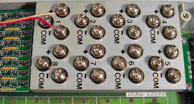
What can you do? The figure below is a rare example of a cold junction system that works well. We originally designed it in 1984, but unfortunately it has not been used by others.
Data acquisition device with minimal cold junction errorfoam insulation.
The thick aluminum heat sink keeps all the screw terminals, where thermocouples connect, at the same temperature as the cold junction sensor inside (not visible). Tests showed that an air temperature difference of 5 degrees across the plate (large, but it can happen) was reduced to a 0.3 degree error. Without the heat sink the error would have been 5 degrees.
Errors can also be minimized by keeping the air around the connections and the thermocouple wires themselves at a uniform temperature with insulation. In the above example a cover keeps air from flowing across the terminals, maintaining uniform temperature. It helps even more to surround the thermocouple wires with plastic foam insulation.
The most common thermocouples are types E, J, K, N, and T (see table 1). They are inexpensive, operate over a wide temperature range, and have a relatively large temperature coefficient. This makes them useful for most applications and relatively easy to interface. The different types are suitable in different environments depending upon the material they are made from. K and T are perhaps the most common, being suited to a wide range of environments, including air and water.
Table 1 Thermocouples Characteristics
| Type | Material | Range (C) |
|---|---|---|
| E | Nickel, Chromium, Constantan | 0 to 1300 |
| J | Iron, Constantan | -270 to 1000 |
| K | Nickel, Chromium | -210 to 760 |
| N | Nicrosil, Nisil | -270 to 1372 |
| T | Copper, Constantan | 0 to 1300 |
| B | Platinum, Rhodium | -270 to 400 |
| R | Platinum, Rhodium | 130 to 1820 |
| S | Platinum, Rhodium | -50 to 1768 |
| C | Tungsten, Rhenium | 0 to 2320 |
| D | Tungsten, Rhenium | 0 to 2320 |
| G | Tungsten, Rhenium | 0 to 2320 |
For high temperatures the B, R, and S type thermocouples are used. Both wires are made of Platinum alloys, which have a very high melting point, but they are expensive, and, because the materials are similar, the thermoelectric effect is much less, and the temperature coefficient is much smaller. Many data acquisition devices can interface with these thermocouples.
For very high temperatures the C, D, and G thermocouples are used. They are made of Tungsten and Rhenium, which gives them the highest operating temperature. Most data acquisition devices cannot handle these thermocouples, because they do not include linearization for these rarely used types.
Do you have a question about our services, pricing, samples, resources, or anything else?
